
|
General introduction:
|
|
In power system, CT is widely applied in one time measurement and control of current. In normal working condition, the secondary side of CT is almost short circuit, and output voltage is very low. During operation, if the secondary winding is open circuit, or abnormal current flows the primary winding (such as lightning current,
| |||||||||||||||||||||||||||||||||||||||||||||||||||||||||||||||||||||||
|
Application:
| |||||||||||||||||||||||||||||||||||||||||||||||||||||||||||||||||||||||
|
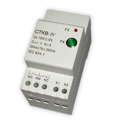
CTKB-IV series CT overload protector is mainly applied in various CT secondary side abnormal over voltage protection, CT secondary side differential winding, over current winding, measurement winding, generatrix protection winding, spare winding etc. | |||||||||||||||||||||||||||||||||||||||||||||||||||||||||||||||||||||||
| Basic principal:
| |||||||||||||||||||||||||||||||||||||||||||||||||||||||||||||||||||||||
|
The basic apparatus of CT secondary open circuit over voltage protection is ZnO voltage dependent resistor, and parallel connection with secondary winding. In normal working condition, voltage dependent resistor is at the sate of high resistance, and the leakage current is very low, while the sample signal is "0'. The control circuit is off operation, and the CT is at the normal working condition. In general condition, secondary winding just has several voltage, and the max. voltage is less than 20V. When CT is secondary return open circuit or primary winding comes forth abnormal over current, the voltage emerged from secondary winding is far higher than the normal condition voltage. Then the voltage dependent resistor is on state ( over 150V), the sample voltage signal is a little higher, and the inner automatic control circuit controls secondary winding short circuit, and active display on the panel. At the same time, it will output remote no power contact signal. When the malfunction is removed, it can operate. There're two reposition methods: one is the malfunction removing of power off, it automatically reposition when restarting the power; another is after the malfunction removing of power on, pushing "reposition" button, it'll remove the malfunction and the circuit will recover before. | |||||||||||||||||||||||||||||||||||||||||||||||||||||||||||||||||||||||
| Technical specification:
| |||||||||||||||||||||||||||||||||||||||||||||||||||||||||||||||||||||||
| |||||||||||||||||||||||||||||||||||||||||||||||||||||||||||||||||||||||
| Connection principal:
| |||||||||||||||||||||||||||||||||||||||||||||||||||||||||||||||||||||||
|
Generally speaking, CT connects A,B,C three phase. The minority connects two phase, and the fews connect single phase. The most is star connection scheme, and the minority is triangle connection. This product is secondary winding star connection scheme. Secondary winding A,B,C accordingly connect with connection terminal A,B,C. A,B,C three phase secondary central point (virtual earth N) connect the "N" connection terminal of CT. If only with A,C winding, B phase can be not connected, and it'll not influence CT operation. It can also be connected with the neutral terminal (virtual earth N). And A, B, C can be connected with every winding. AC, DC 100-240V power connects CT for inner electric parts use. One group of no power output terminal is for customers use, and it can be connected externally with AC or DC. E.g. middle (action) terminal and NC terminal connect with red signal lamp. When the lamp is on, it indicates CT is at normal working condition. The middle (action) terminal and NO terminal connect with "red" lamp or warning device. When it's operating, it indicates CT detects some secondary winding is malfunction of open circuit. | |||||||||||||||||||||||||||||||||||||||||||||||||||||||||||||||||||||||
| Inspection and operating method:
| |||||||||||||||||||||||||||||||||||||||||||||||||||||||||||||||||||||||
| ① Before operating, CT should be inspected. When the multi-meter resistance measures A (or B or C) and N terminal, the resistance should be over tens of megohm. | |||||||||||||||||||||||||||||||||||||||||||||||||||||||||||||||||||||||
 | |||||||||||||||||||||||||||||||||||||||||||||||||||||||||||||||||||||||
|
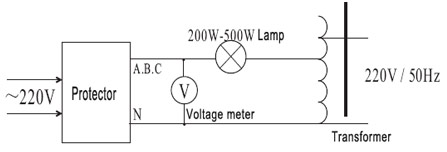
② When the protector is in testing process, the circuit should be connected as per the above drawing, then adjusting the transformer to OV position. When switching on AC 220V power, the protector should be "reposition" automatically. The yellow light on the panel should be on, and others should be off, which indicates that every circuit is "reposition". If there's red light on, it indicates that some are not "reposition" automatically. When pushing the "reposition" button, it'll "reposition" automatically. Then turning transformer handle slowly to increase the voltage, when the voltage is up to rated value, the load light will be suddenly on, and the red light with the same phase on the panel will be on too. Then adjusting the voltage lower, some of the lights will be not off, it indicates that CT protector with this phase is open circuit, the protector is short circuit, and operating is normal. In general situation, the voltage when lights are on is lower about 10% than the working voltage of CT protector. ③ As per the above operation method, every phase circuit should be inspected. Connecting as per the connection principal and connection terminal. When the inspection is no problem, it can be switched on. | |||||||||||||||||||||||||||||||||||||||||||||||||||||||||||||||||||||||
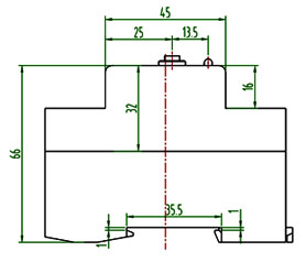
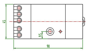
| Dimension:
| |||||||||||||||||||||||||||||||||||||||||||||||||||||||||||||||||||||||
 |
 | ||||||||||||||||||||||||||||||||||||||||||||||||||||||||||||||||||||||

 Chinese
 Russian
 German
 Spanish
 French
 Italian
 Portuguese
 Japanese
 Indonesian
 Vietnamese


 Add to Inquiry Basket
 View Inquiry Basket
 The products that you selected had been put into inquiry basket !
